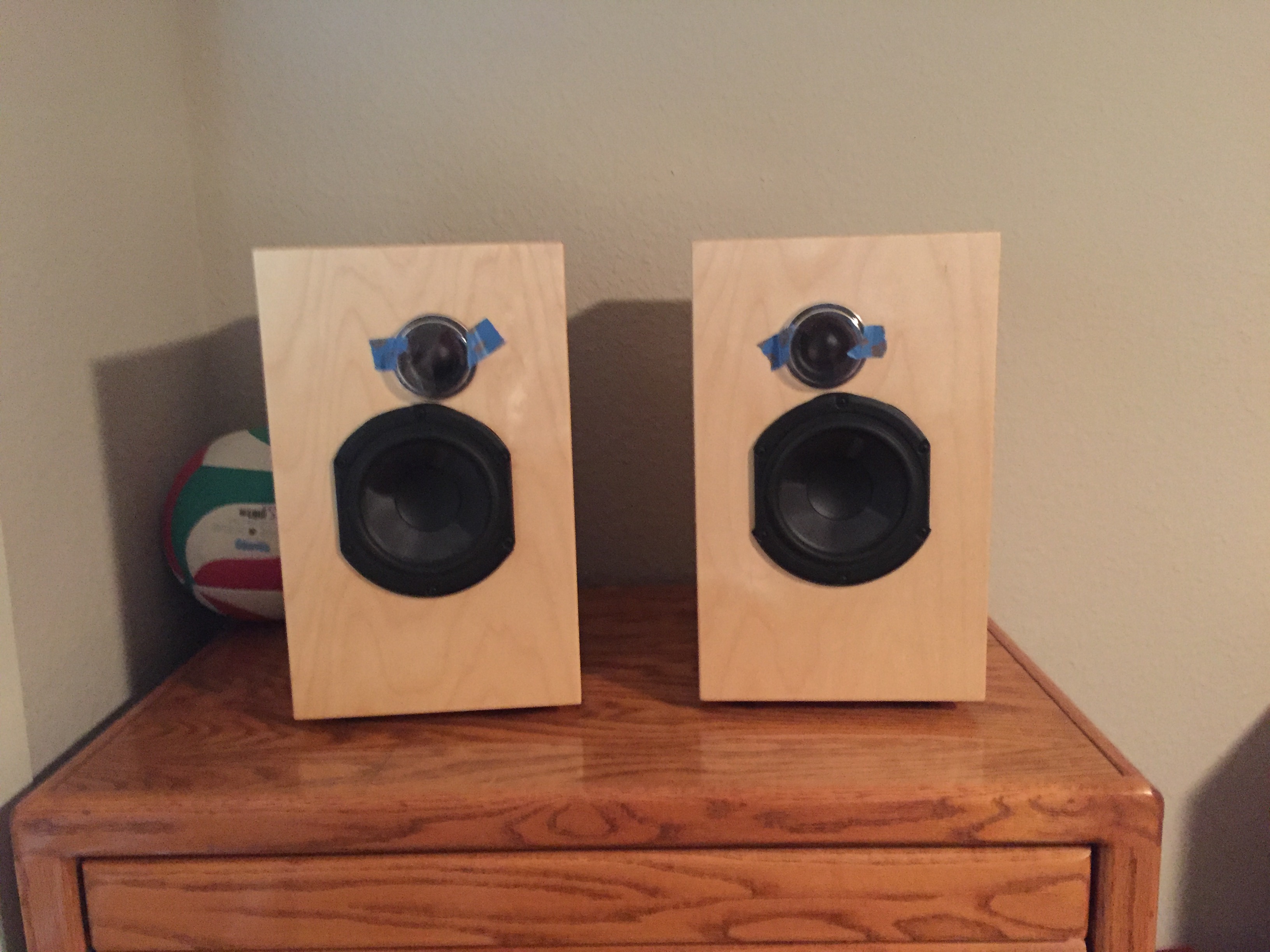
TWO-WAY MONITOR SPEAKERS
- Build two-way monitor speakers from rough instructions and exploration of available designs.
- Document and update the build process as I see fit.
- Create CAD drawings of speaker enclosure and components.
- Analyze the final product using microphones and test signals.
Note:
This project is a work in progress, and my focus is currently elsewhere. To see a similar, completed project, see my Bass Reflex Modelling project here.
Step 1: Design
As a graduation gift, I was given a Bluebird Audio two-way monitor speaker kit by Louis Pandula which he designed. Included were drivers, crossover schematics, and documentation of his build of the same speakers. I have been following these specifications during my build, but have made modifications to the construction and design where I see fit. I have also been laying out the design using AutoCAD, and hope to improve the process of building these speakers. As such, the main focus of this project has been designing the manufacturing processes to build and assemble speakers from general specifications of drivers, baffles, and enclosure volume.
Step 2: Constructing the Enclosures
The first step in construction is to choose the enclosure material. I chose to use 3/4" Baltic Birch plywood, which has many thin birch plies and is thus more rigid than other plywoods, making it better for audio applications. From the dimensions of the speaker enclosures, a pair of speakers could be made from a 4' x 4' board. I used a 5' x 5' that was lying around in the garage, and laid out the pieces as shown in **board diagram**. This layout keeps resetting the tablesaw fence to a minimum, minimizing the time spent working with large pieces of wood. Once the three pieces were ripped on the tablesaw, each piece was cut at the secondary dimensions. For a repetitive task like this, I set a stop (a clamped piece of scrap wood) on the chop saw fence at the desired dimension from the blade, which sped up this process as well.
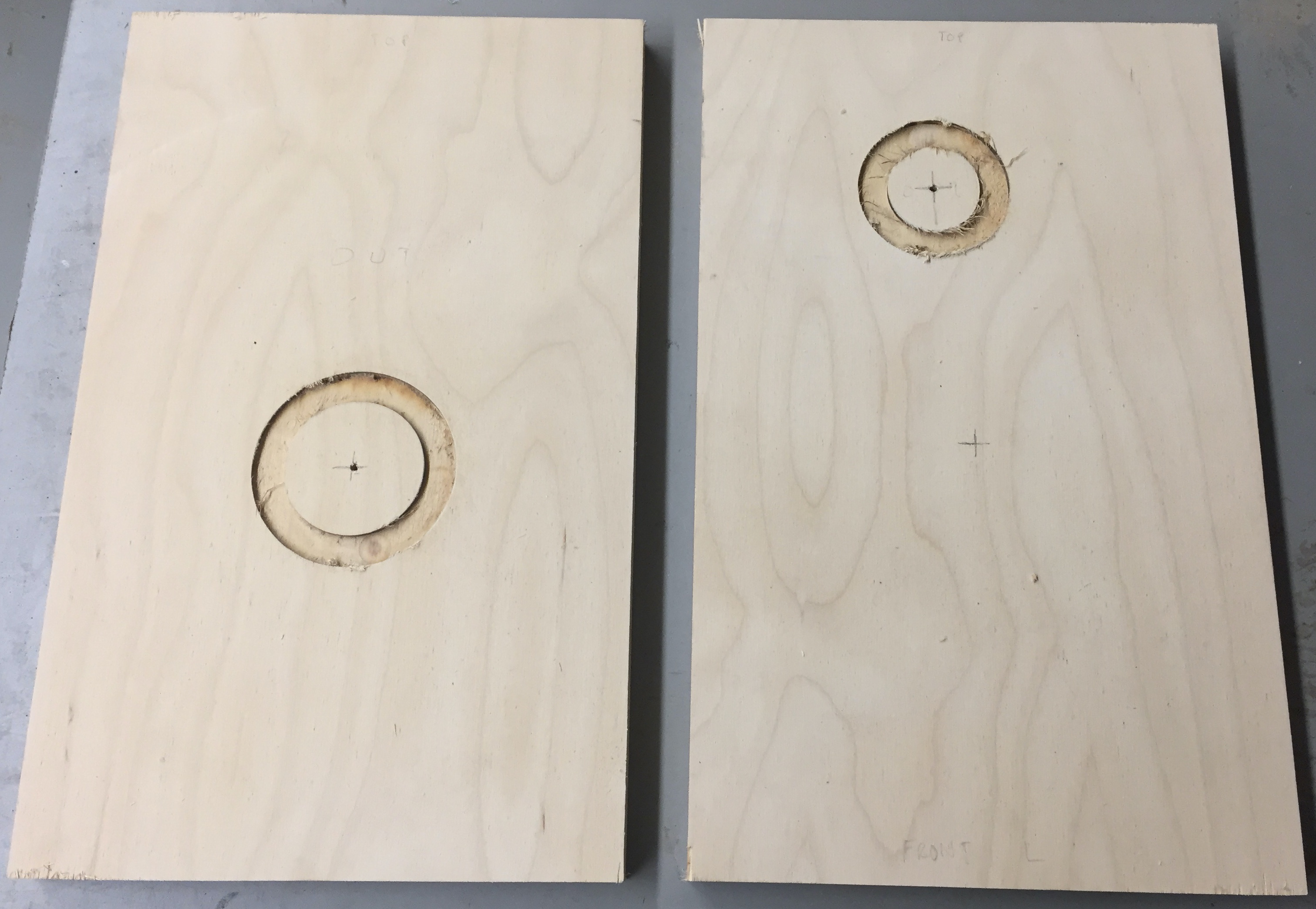
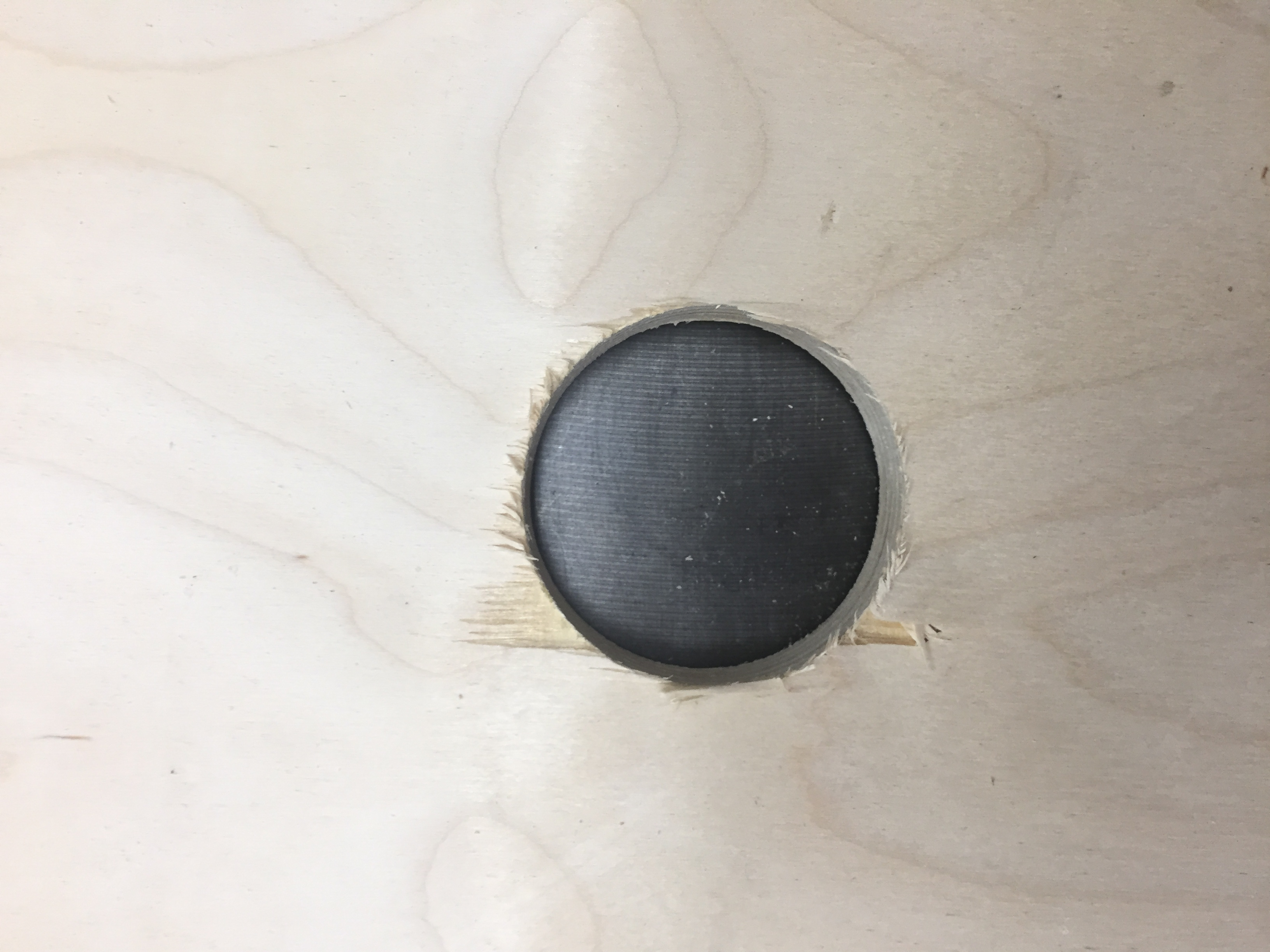

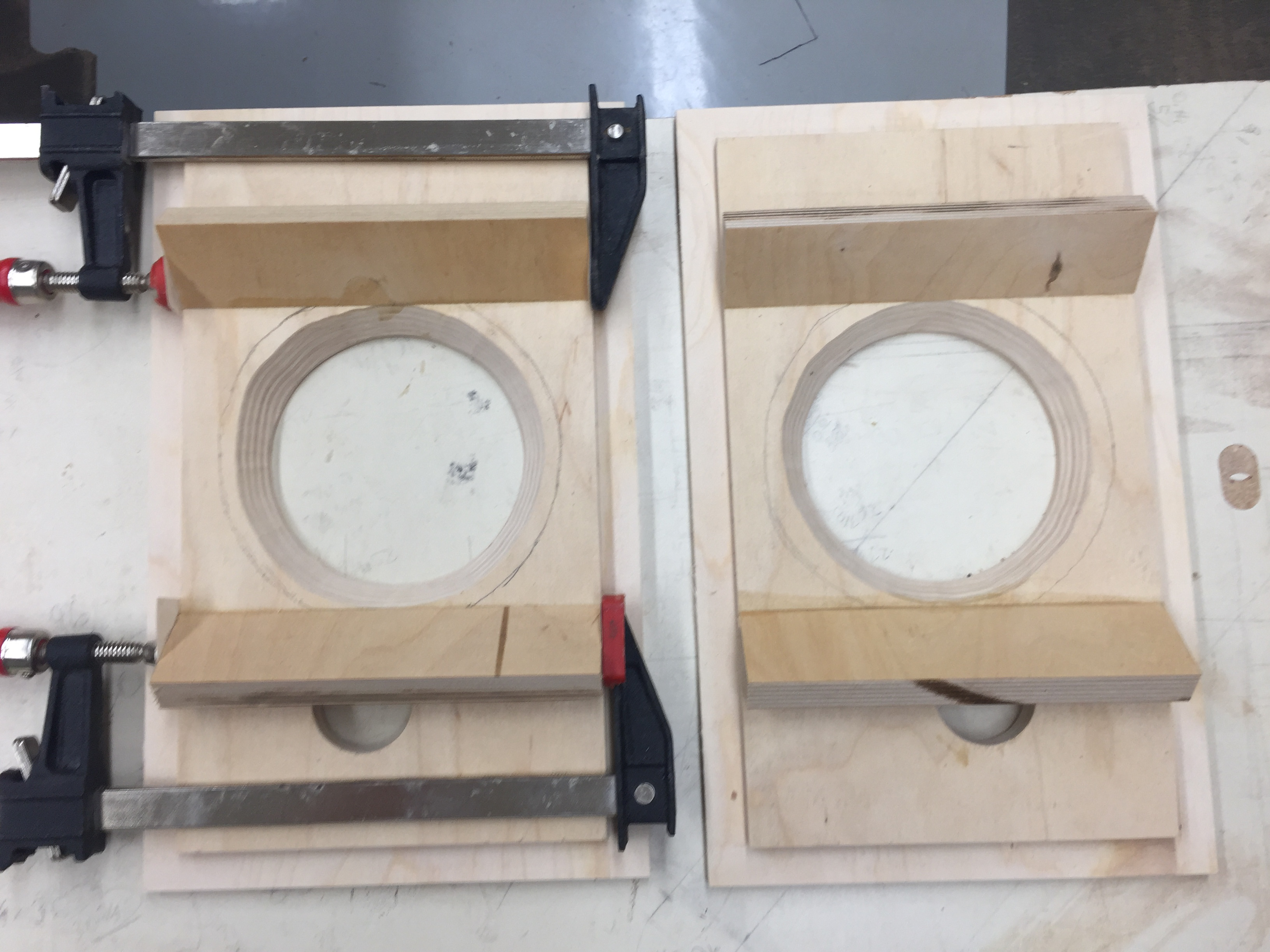
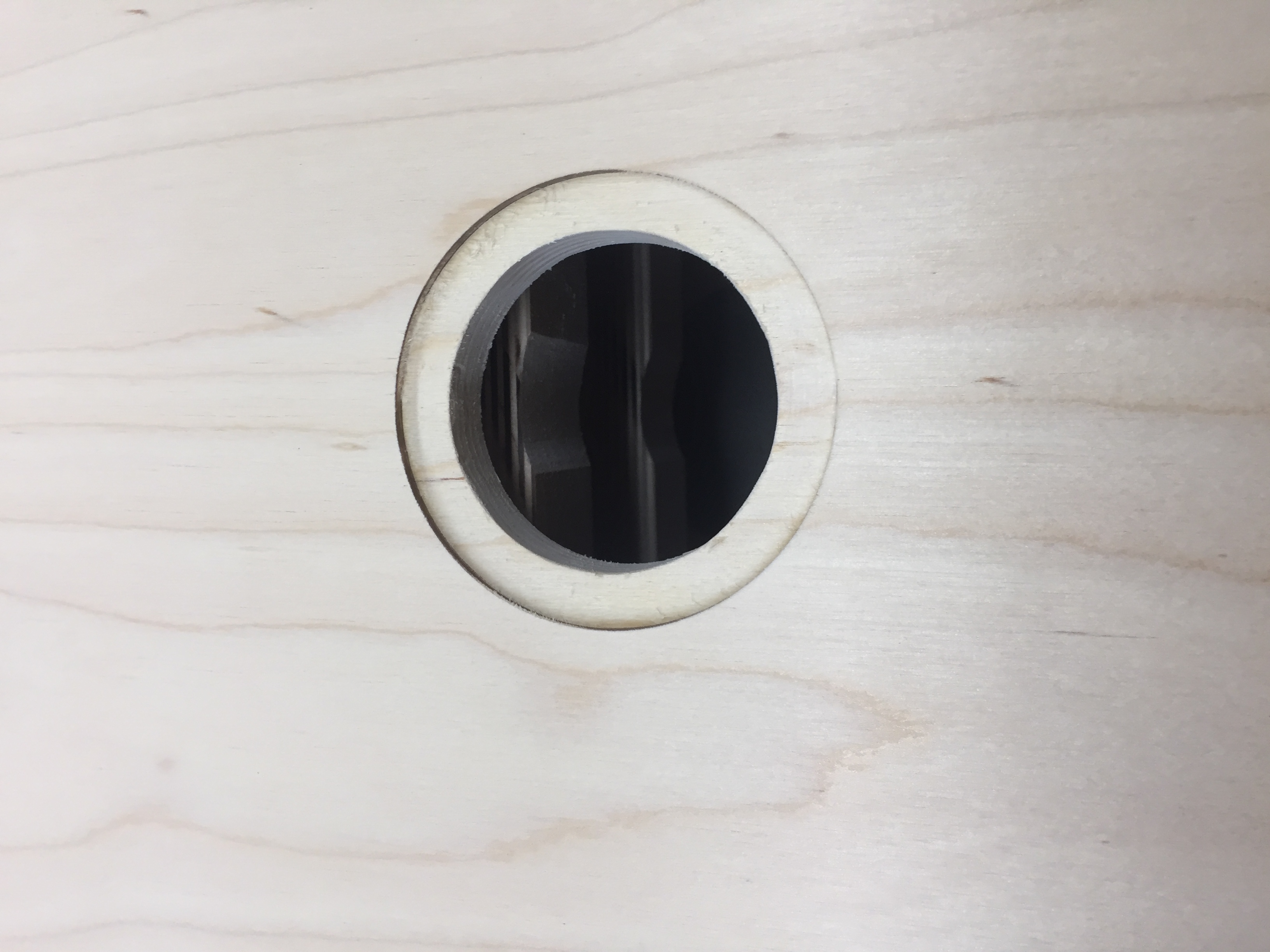
Once the enclosure panels were cut to the correct dimensions, it was time to cut the driver and port holes in the front and back panels. These circular holes are too large in diameter for a hole saw or Forstner bit, and some need a counterbore so that drivers/ports mount flush to the cabinet face. This was made with a circular jig and router, and done in a continuous cut around the circle to keep a clean edge (since the router was handheld, this meant walking around the edge of the table while cutting). Once the counterbores were made at the desired dimensions, the circular cutting bit (shaped like a T) was set up in the drill press (with a scrap board underneath to save the table) and used to cut the through holes. To minimize blowout/tearout on the back of these holes, the hole depth was cut to around 75% through on one side, and then the piece was flipped over, and the hole was finished from the other side, centering it with the central bit. By starting this from the outside of the enclosure panels, this method kept exposed cuts clean.
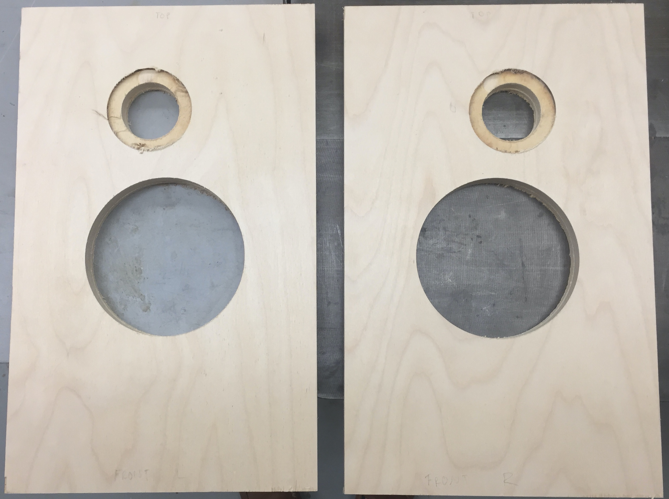
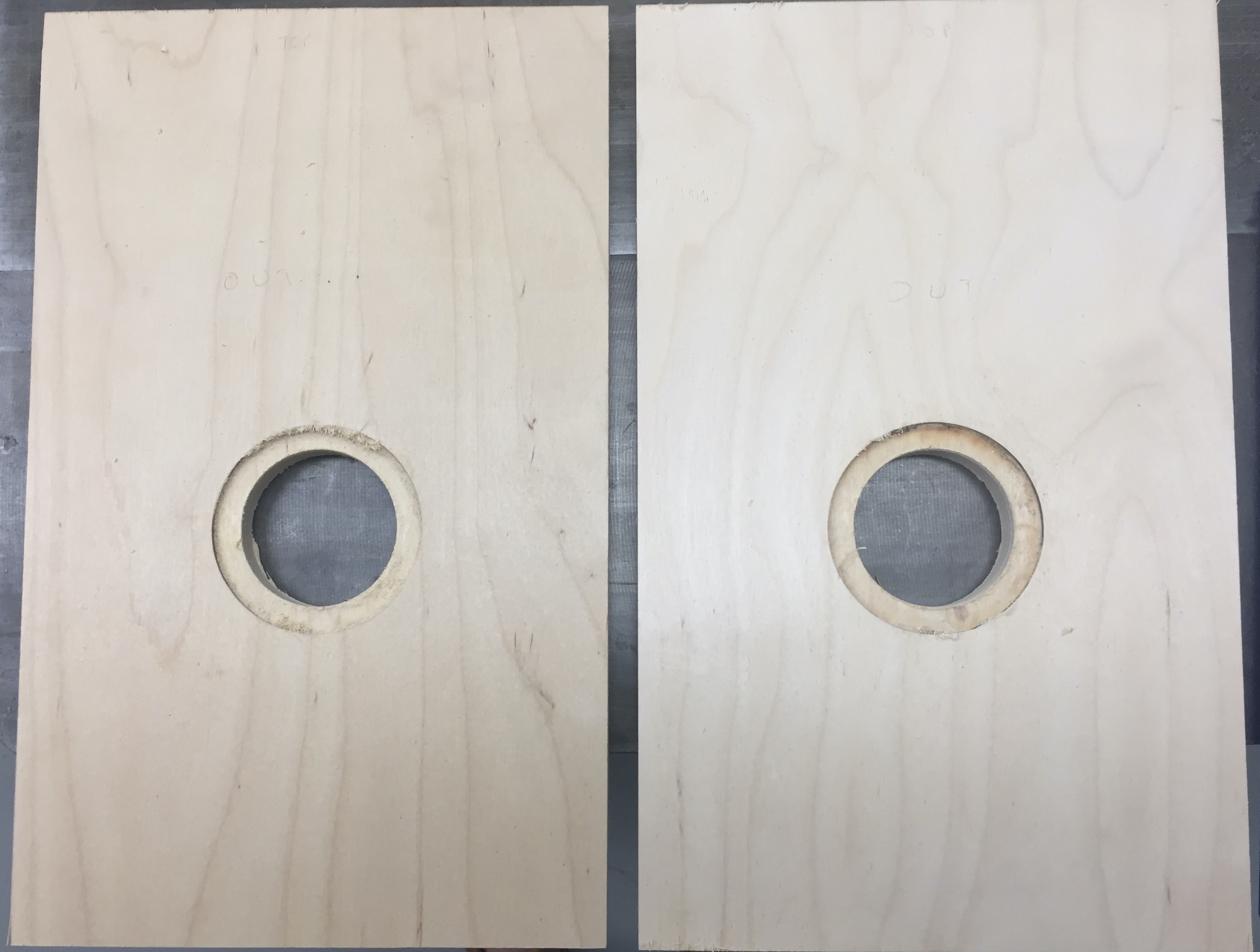
After the through holes were cut, the next step was to put a 45 degree chamfer on the backside on the hole of the largest driver. This was especially important because of the thick wood I chose to use, as any neck between the transducer and the main volume of the enclosure would impart extra acoustical mass (equivalent to an inductor in the electrical model) onto our combined speaker model. The chamfer removes enough material that the transducer has direct line of sight to the enclosure walls, allowing it to be modelled as an acoustic compliance (equivalent to a capacitor in the electrical model). I chose to do this on a spindle sander with an adjustable-angle bench, because it quickly removes material and is easily adjustable by hand. Furthermore, since the chamfer is on the inside of the enclosure, any non-uniformities in appearance from the sander will be hidden from view. The chamfer depth was controlled with a reference line on the rear side of the piece, ¾” larger than the radius of the through hole. To keep the structural integrity of the enclosure, the chamfer was made to be around ½” in on each dimension.
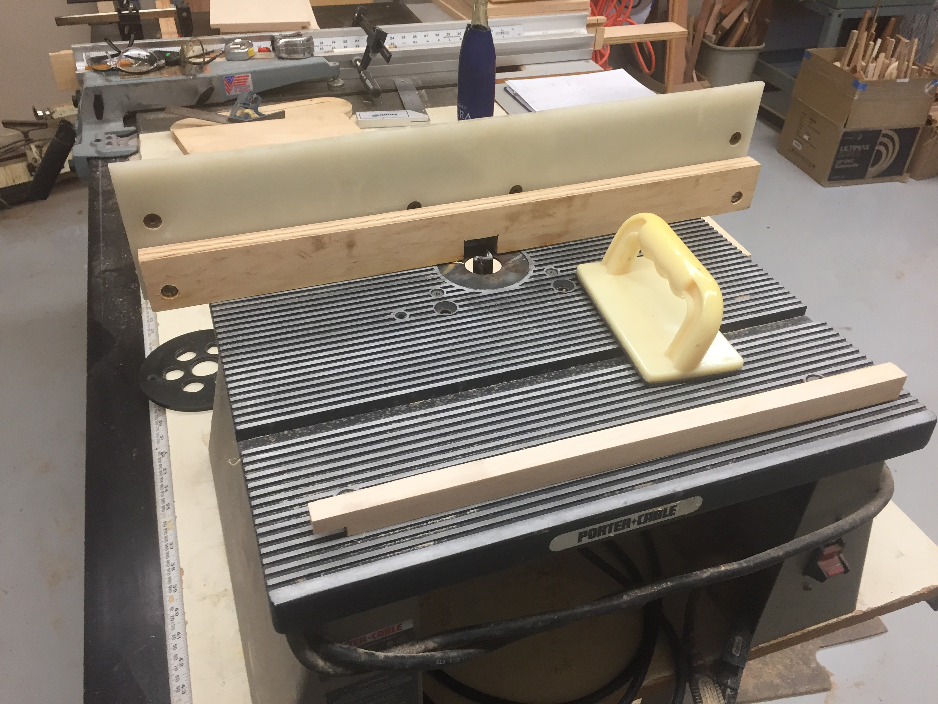
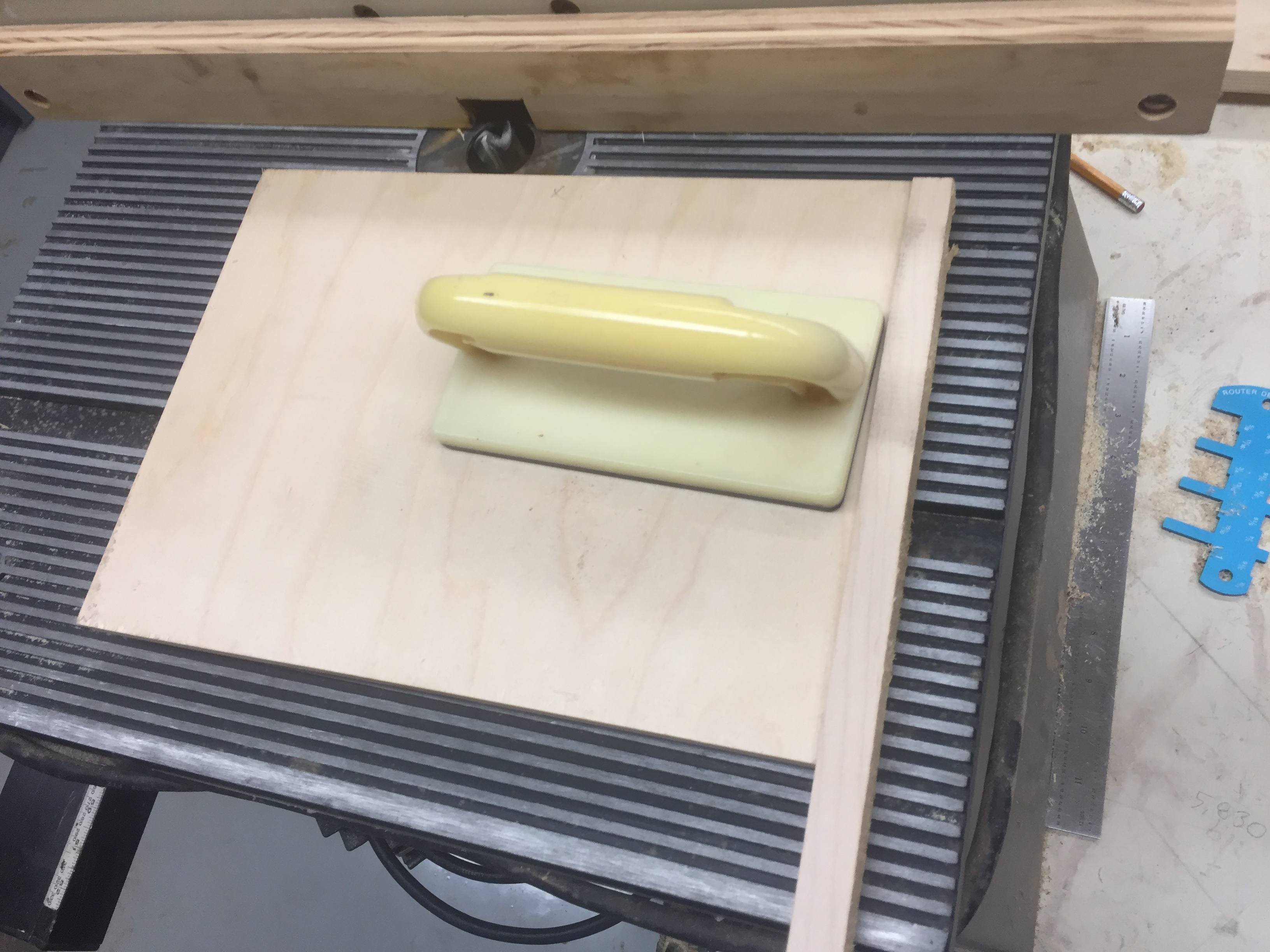
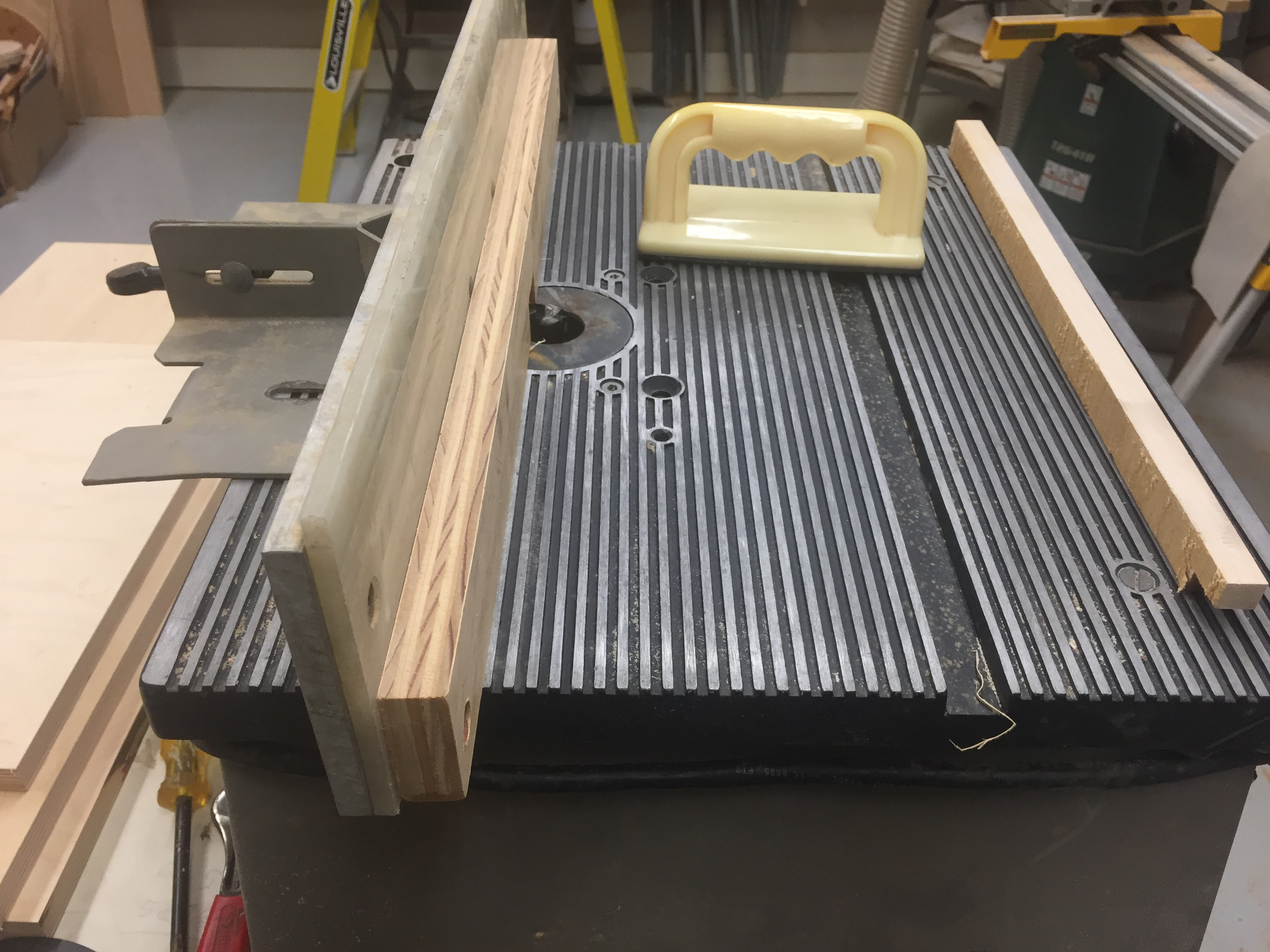
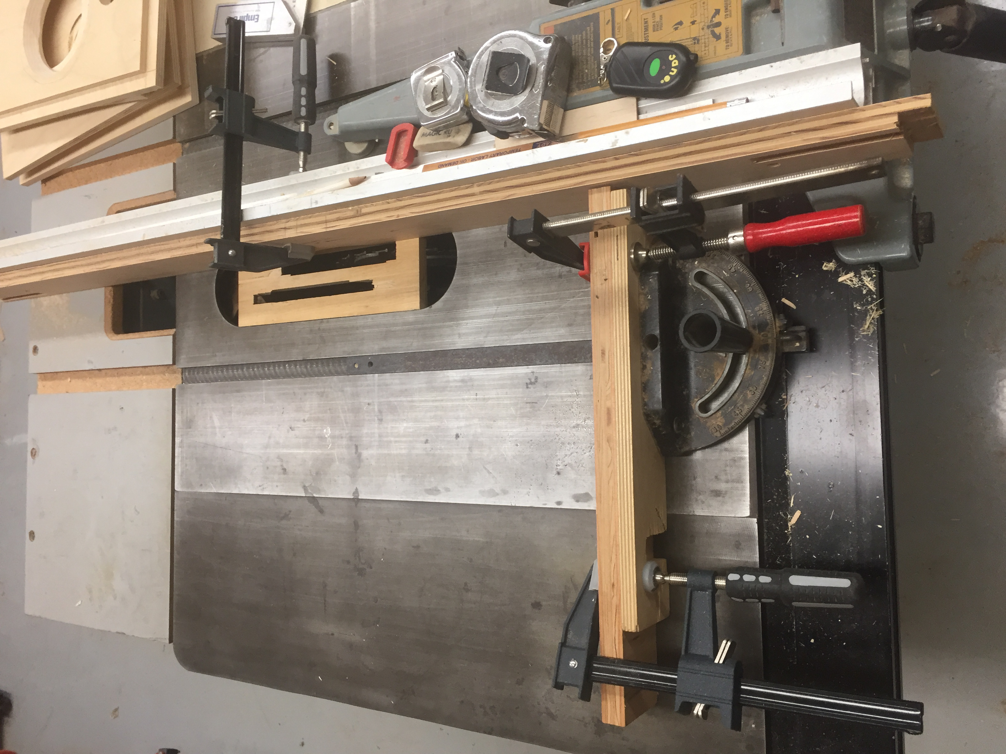
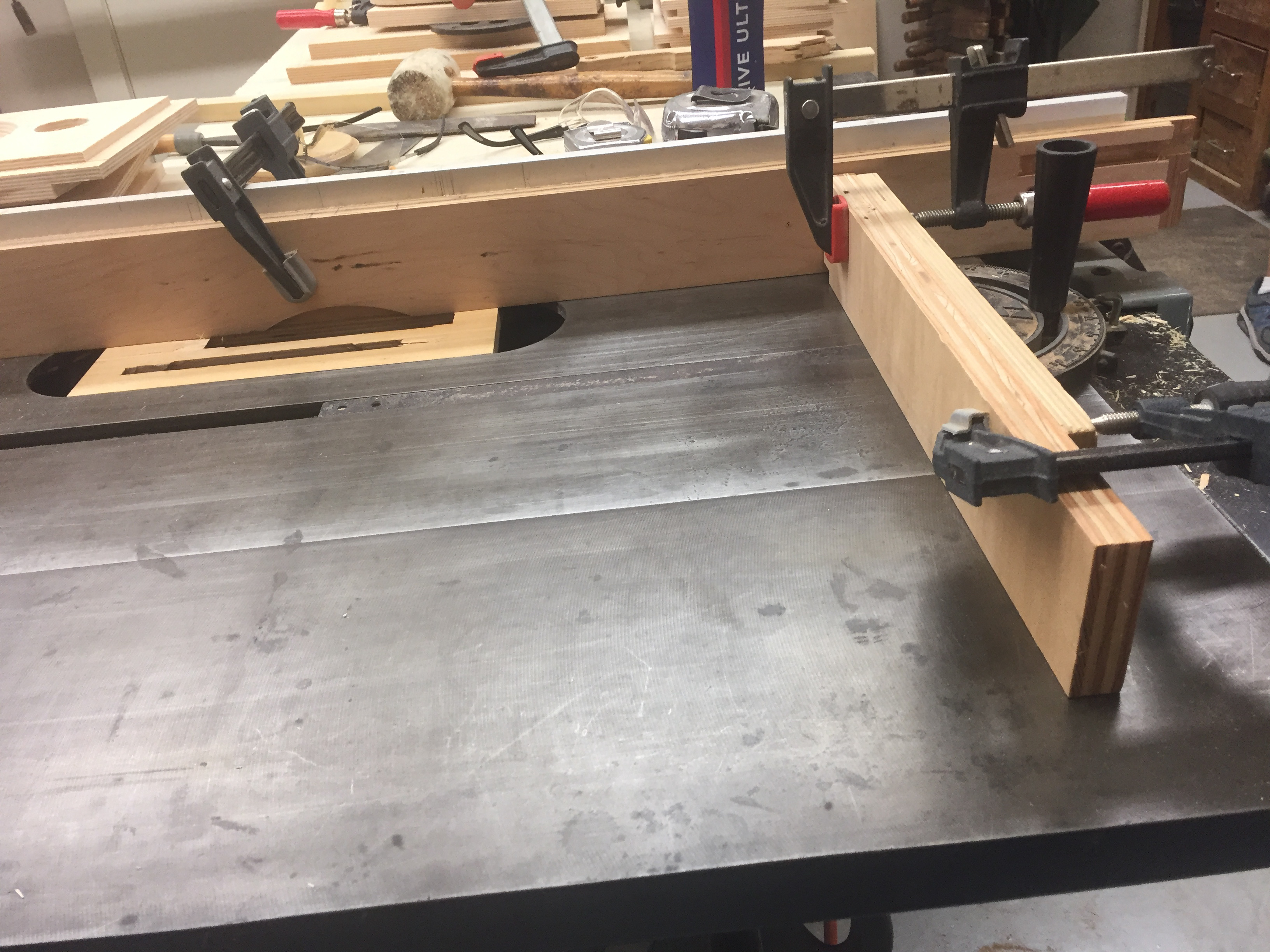
Now that the interior features of the panels were finished, the rabbet joints for the outer panels were cut. Since these joints will be exposed in the final speakers, it is especially important to prevent blowout or accidental damage to these edges. Cutting these last minimizes the chance of accidental damage to these edges, and keeps a clean, straight edge while cutting the center holes, which allows for easy clamping. The dimensions of these rabbets are large thanks to the ¾” plywood used, making these tricky to cut. Using a router on a table (as shown, with an extra wood fence to set the bit depth) is usually a good method of making many rabbets of the same dimensions, but the ~¾” depth required causes the cut to be slow and the bit to burn the wood. After one cut, I decided to drop the router bit to ⅜” and do the cut in two halves, but this makes the entire process take twice as long. To speed things up, I set up a dado blade on the tablesaw, with another wood fence to adjust the depth. With this setup, cutting at ¾” hieght is much faster thanks to the larger blade, and a miter gauge (with an extra fence) can help keep cuts square. The drawback of cutting rabbets on a tablesaw is that the blade will sometimes push the piece up, creating a less uniform rabbet than on a router. To fix this, we cut the majority of the rabbet on the tablesaw (to ~1/16” under the desired dimensions), and then finish the cut on the router table set at the final dimensions. This is what I ended up doing, which produced great tolerances on the final rabbets. One thing to note is that the router table can still blowout the edges of the rabbets despite the small amount of material removed. To prevent this, a sacrificial piece of scrap wood was clamped to the end of the panel (though slightly off of the fence), which prevents this from happening. Another possible problem is not enough vertical pressure applied while cutting, especially near the end of the cut. This allows the board to lift off of the table surface, which makes the rabbet uneven, but is easily corrected by running the board through again with enough pressure.
A quick note when using a router: it is extremely important that sawdust is quickly evacuated from around the cutting bit to ensure a smooth cut and prevent burning. I did this with a shopvac wedged into the back of the fence, but the most influential factor in this is cutting speed. Pressure should be applied to move the bit into the wood, but not so much that the router strains to remove the offcut material or binds into the wood. I use the sound of the router as a gauge of cut speed; you can hear the bit spinning freely or binding against the piece and adjust your cut as needed.
The front baffles are two small horzontal pieces coming at a 45 degree angle out of the chamfered center hole, to direct sound towards the rear of the enclosure rather than along the front edge. The angled edge was cut on the tablesaw, and trimmed to size on the chop saw. After these were glued, the edges of the enclosures can be glued into place. All sides of the enclosures will be glued together, with the exception of the back panel, which will be attached with screws to allow access to the internals of the enclosure.
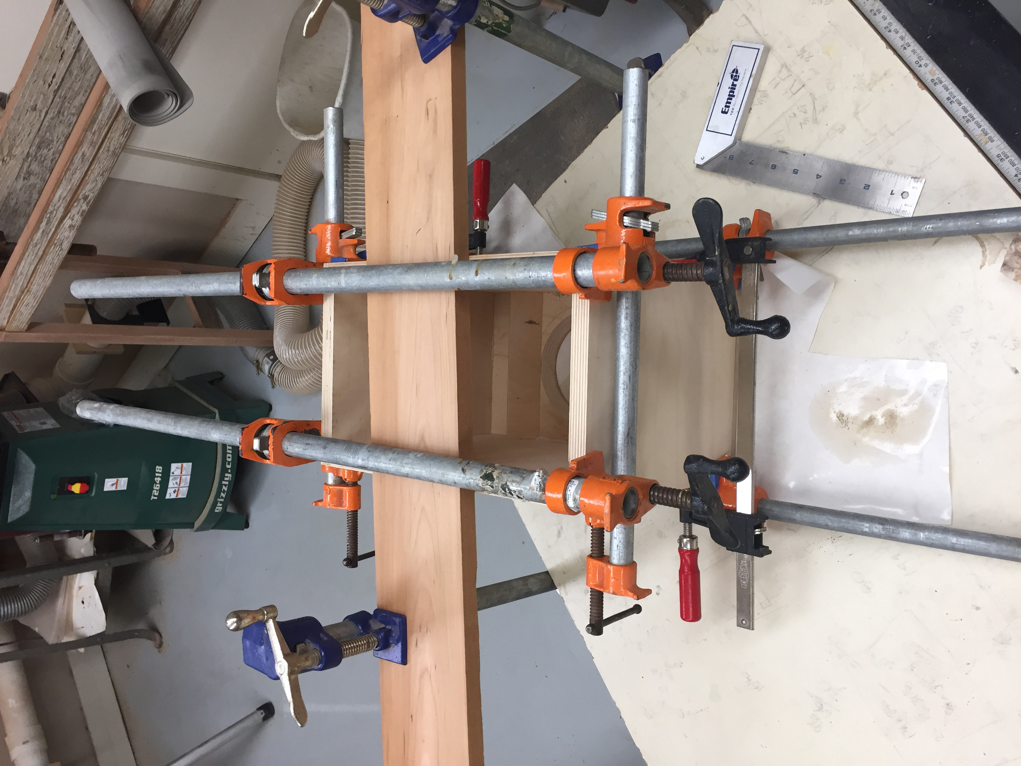
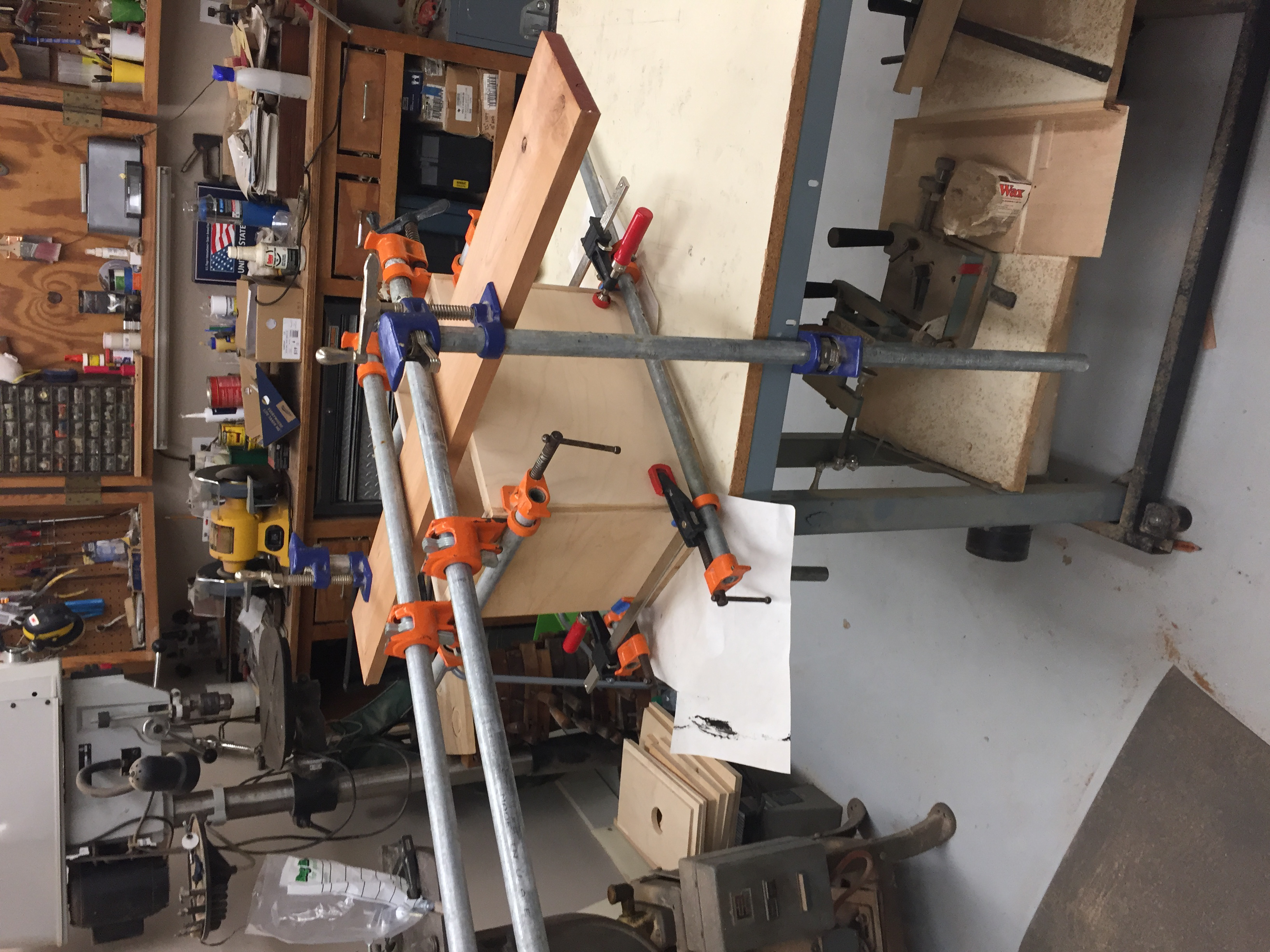
Gluing the enclosure panels is always a tricky process, especially when done working alone. Once you find room for clamps in every direction, you must then fasten each clamp so that it is tight enough to stay in place, but not too tight as to pull other pieces out of alignment. On top of this, the whole process is timed by the glue (Titebond III gives ~10 minutes of working time), so I lay out my pieces and clamps in position before starting to work with the glue. Once I apply the glue, it becomes a relatively quick process of putting everything in place, and then adjusting clamps until everything is square. Of course, this process plus the fact that not all pieces are perfectly square makes it almost impossible to get perfect joints on all sides, but seems to minimize gaps well enough. Any remaining gaps will be filled later with putty, so I am mostly concerned about getting each piece square rather than eliminating gaps. Finally, because the joints are rabbeted, visible gaps on the outside of joints are only half the depth of the panel thickness, and will not affect the enclosure's acoustical integrity. Overall, the 4 sides were almost perfectly square with each other, but the front panel was lifted in opposite corners. I was happy with the way the first enclosure turned out, but enlisted extra help to glue the second enclosure to lessen my stress while applying glue.
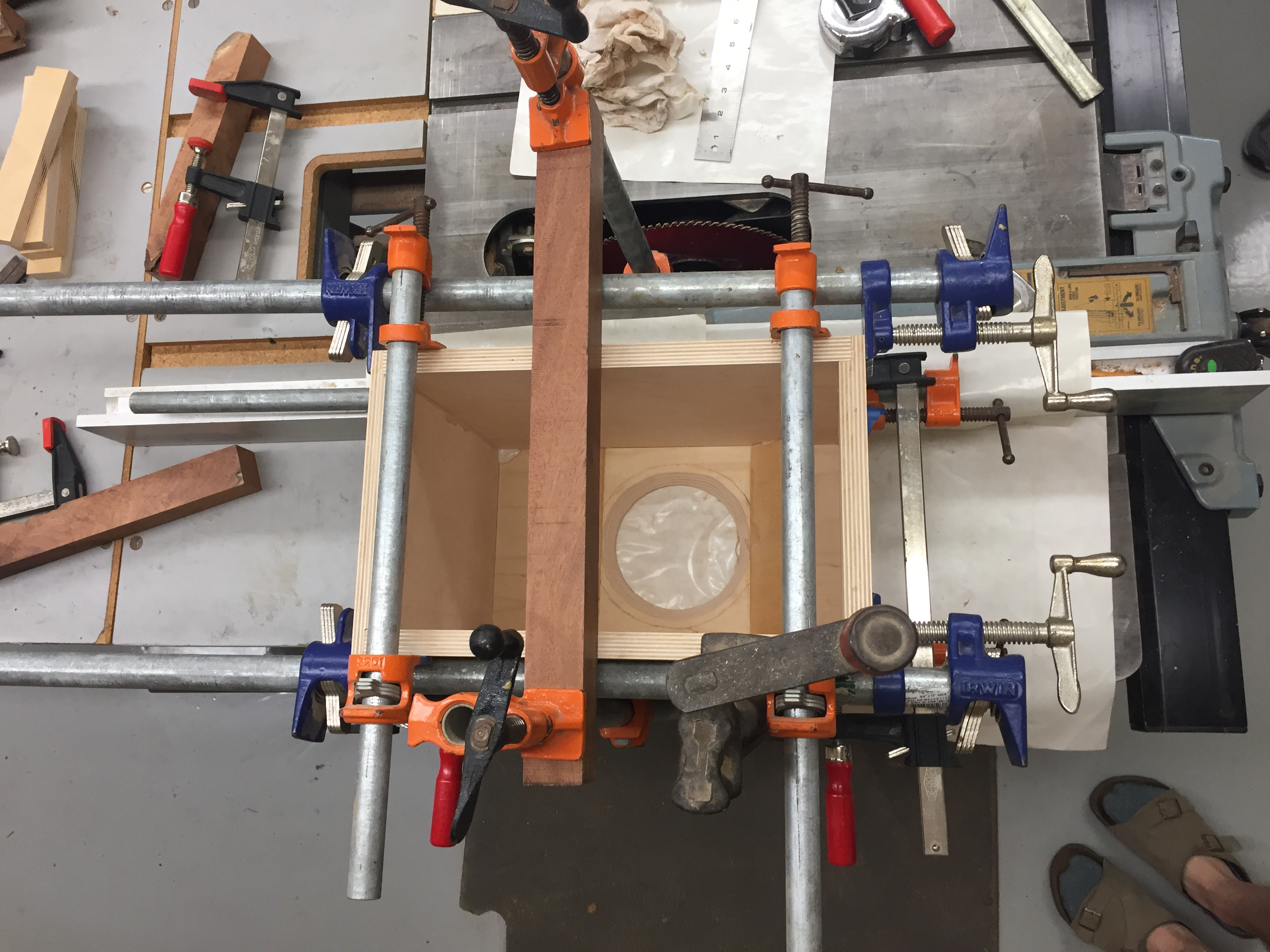
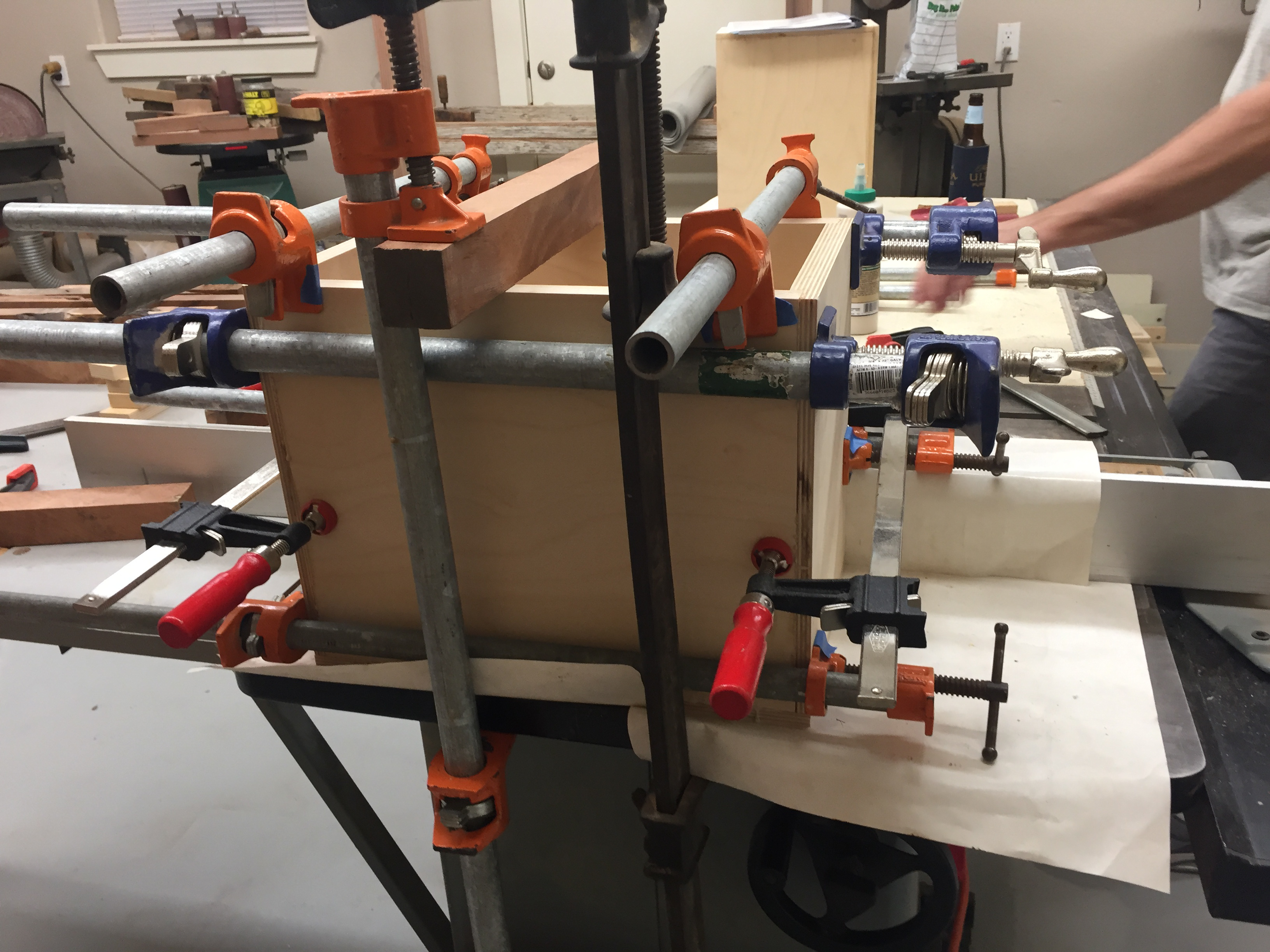
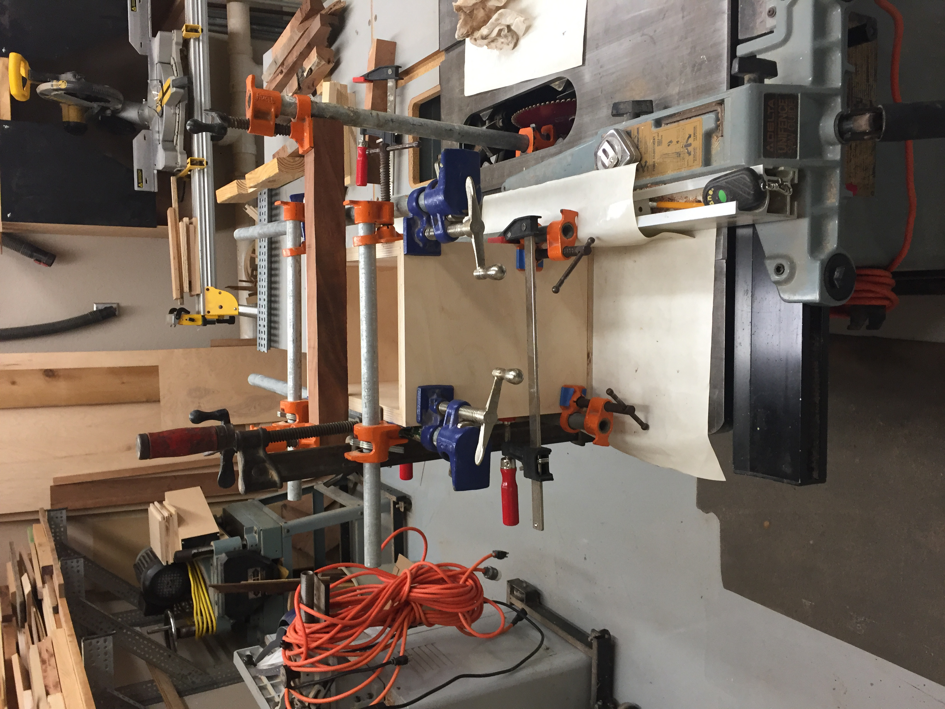
For the second enclosure, I used the tablesaw fence as a right angle guide for the back corner of the enclosure. In theory, this should lessen the number of clamps that need to be placed to keep that joint square, but in practice did not help very much. This guide actually prevented clamps from applying enough downward force on the enclosure walls, leaving a hairline gap along part of the edge. Luckily, this will not negaltively affect the speaker's performance here, but is not visually appealing. However, the cabinet face is much more square with the side panels than the other enclosure, so the guide did accomplish its purpose. In the future, I will probably use a guide again when gluing rabbet joints, and just fill in any gaps later.
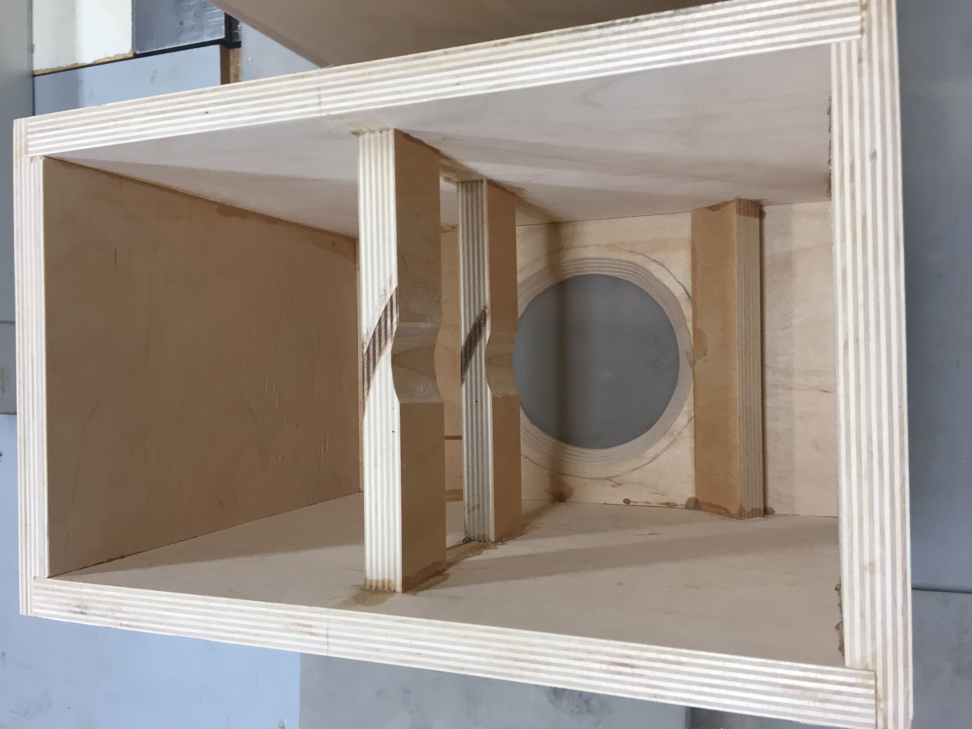
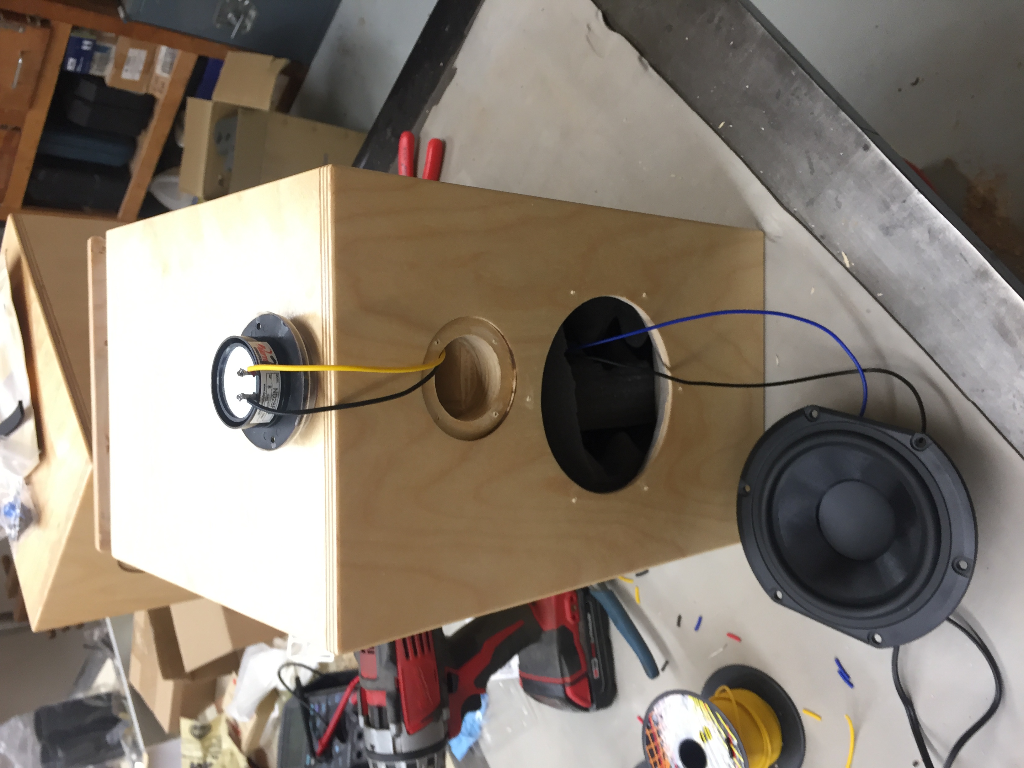
After gluing the internal braces, I realized that they slightly collide with the drop-in port on the back panel of the enclosure. To fix this, I chose to contour the braces to match the port cutout, which solved the problem. This was done with a 2 1/4" diamtere drum on a spindle sander.
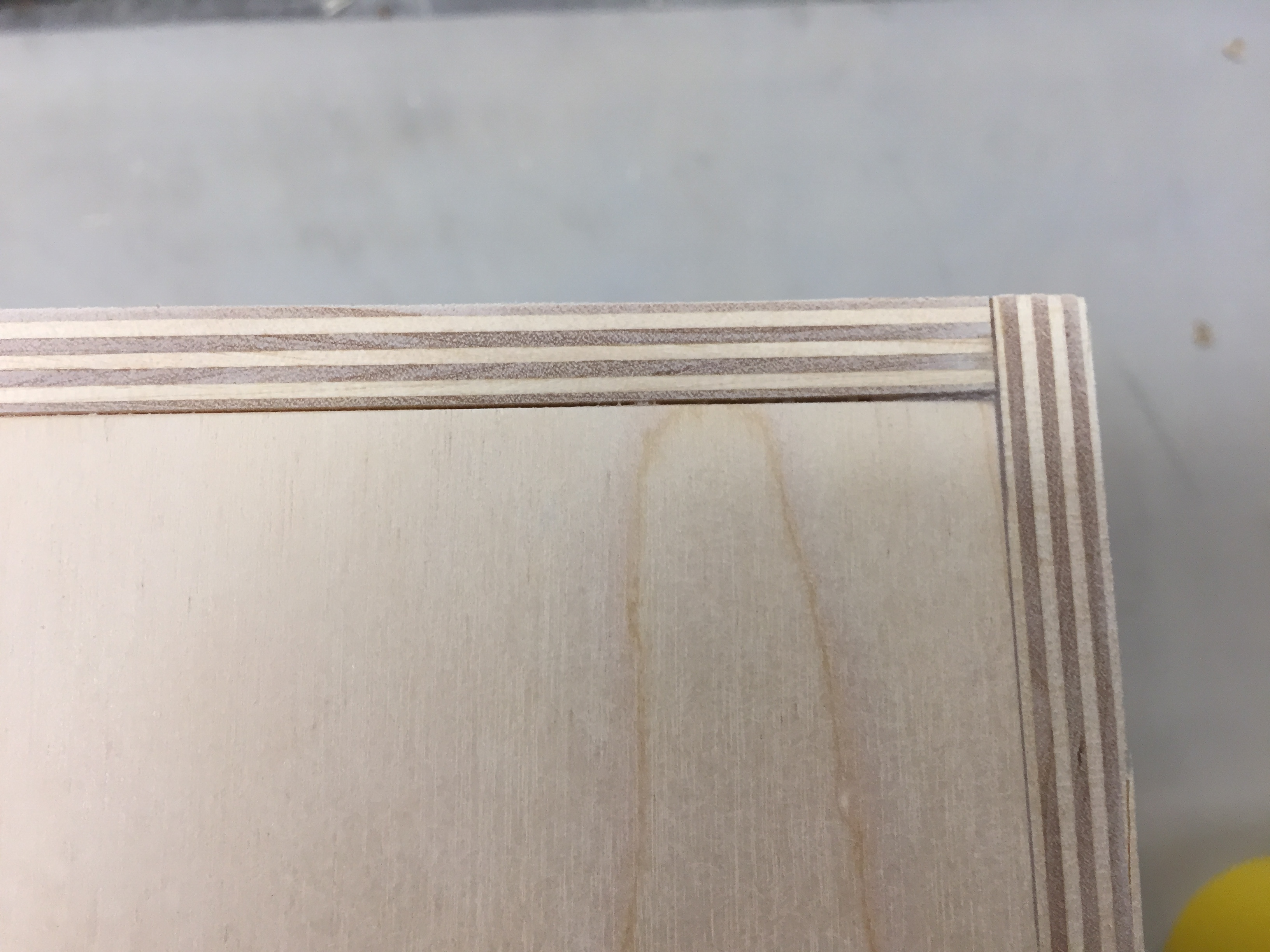
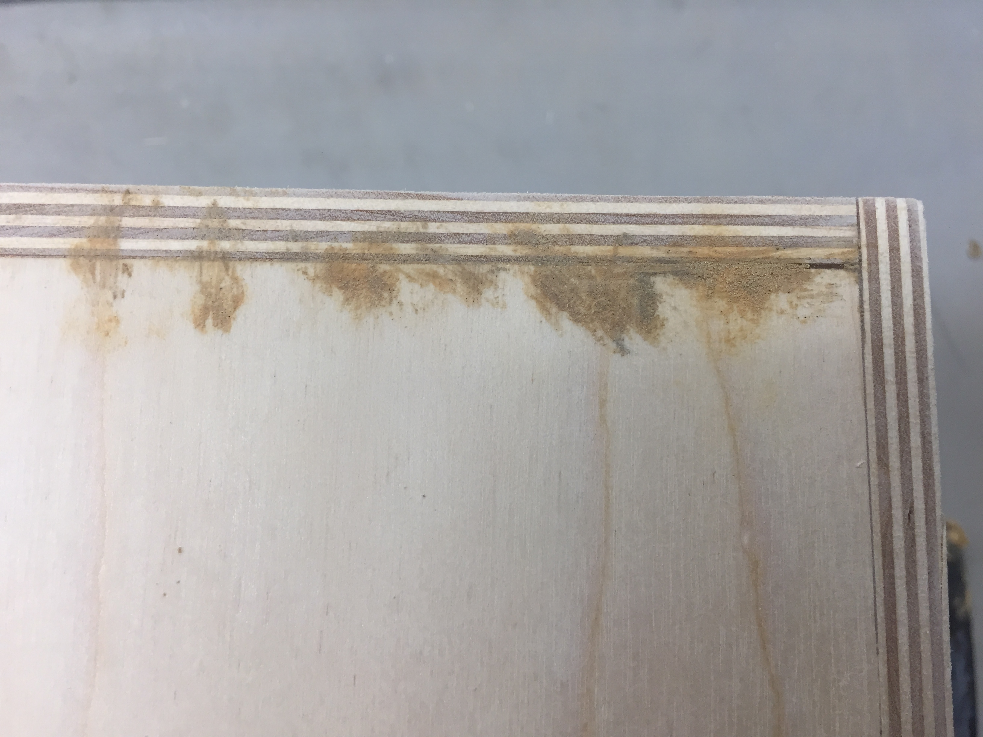
After an initial sanding with 80 grit sandpaper, any gaps between the panels were filled with wood filler. This is purely for cosmetic purposes, as the rabbet joints provide a seal on all panels despite these gaps, but will keep the enclosures from looking cheap.
Before finishing the surface sanding, I raised the grain with a sprayed coat of water. The raised grain was then sanded down with 220 grit sandpaper, to give the smoothest finished surface possible. If this step is skipped, the grain will raise once you start applying the finish, and the surface will end up rough to the touch.
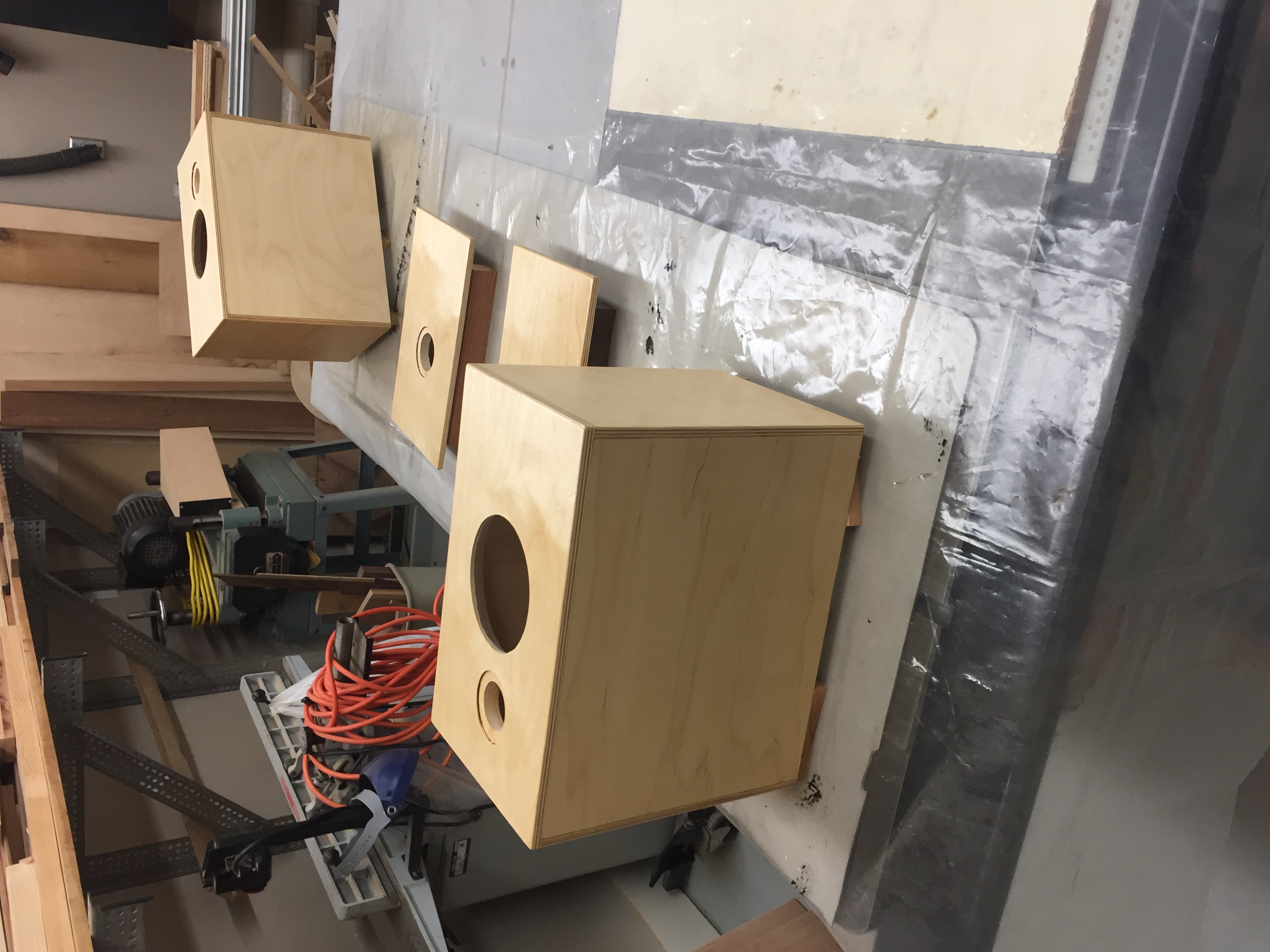
I put 5 light coats of shellac to finish the enclosure surface, leaving plenty of time between applications and lightly sanding any rough spots. It is important to finish the wood parts of the enclosures before installing any other parts, otherwise you may damage or overspray onto your drivers.
Step 3: Constructing the Crossovers
Now that the enclosures are completed, the crossovers need to be assembled and mounted on the inside of the enclosures.
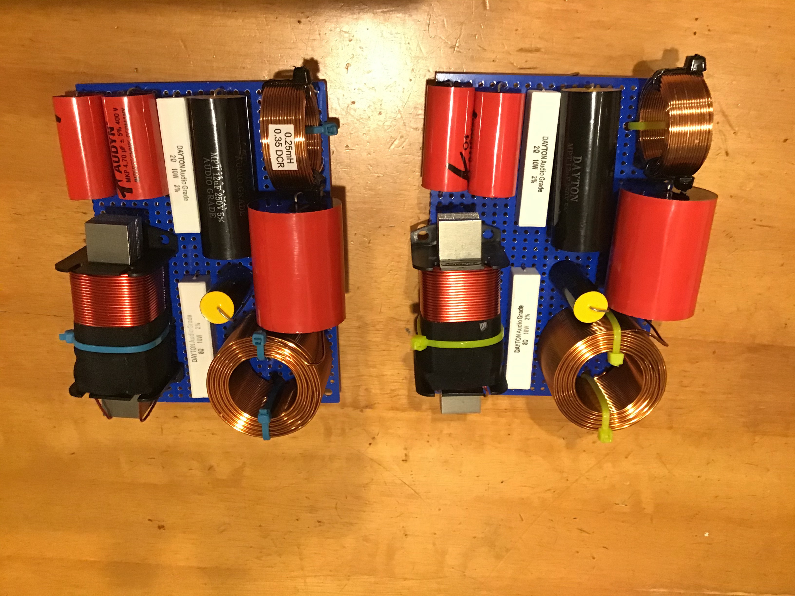
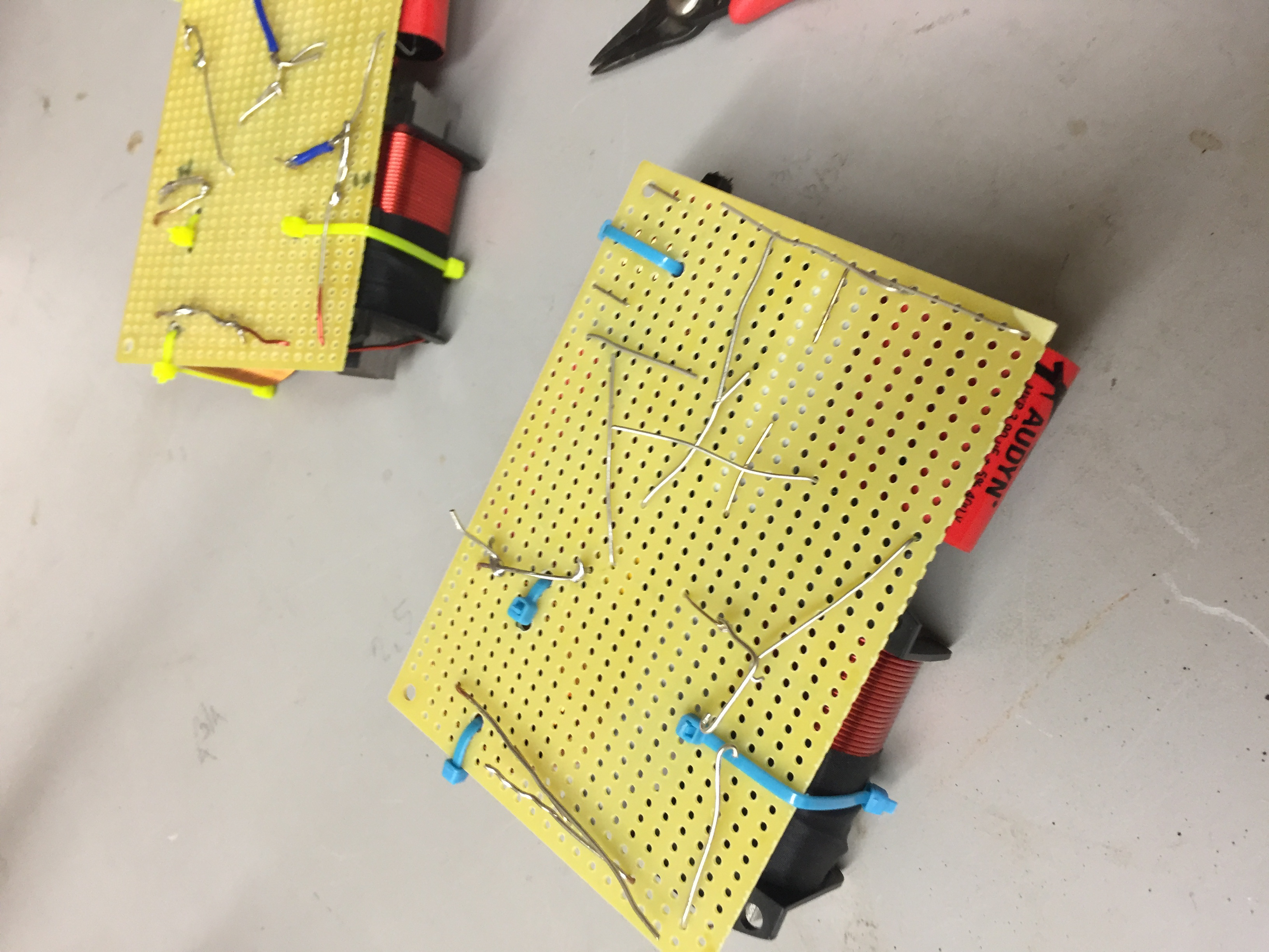
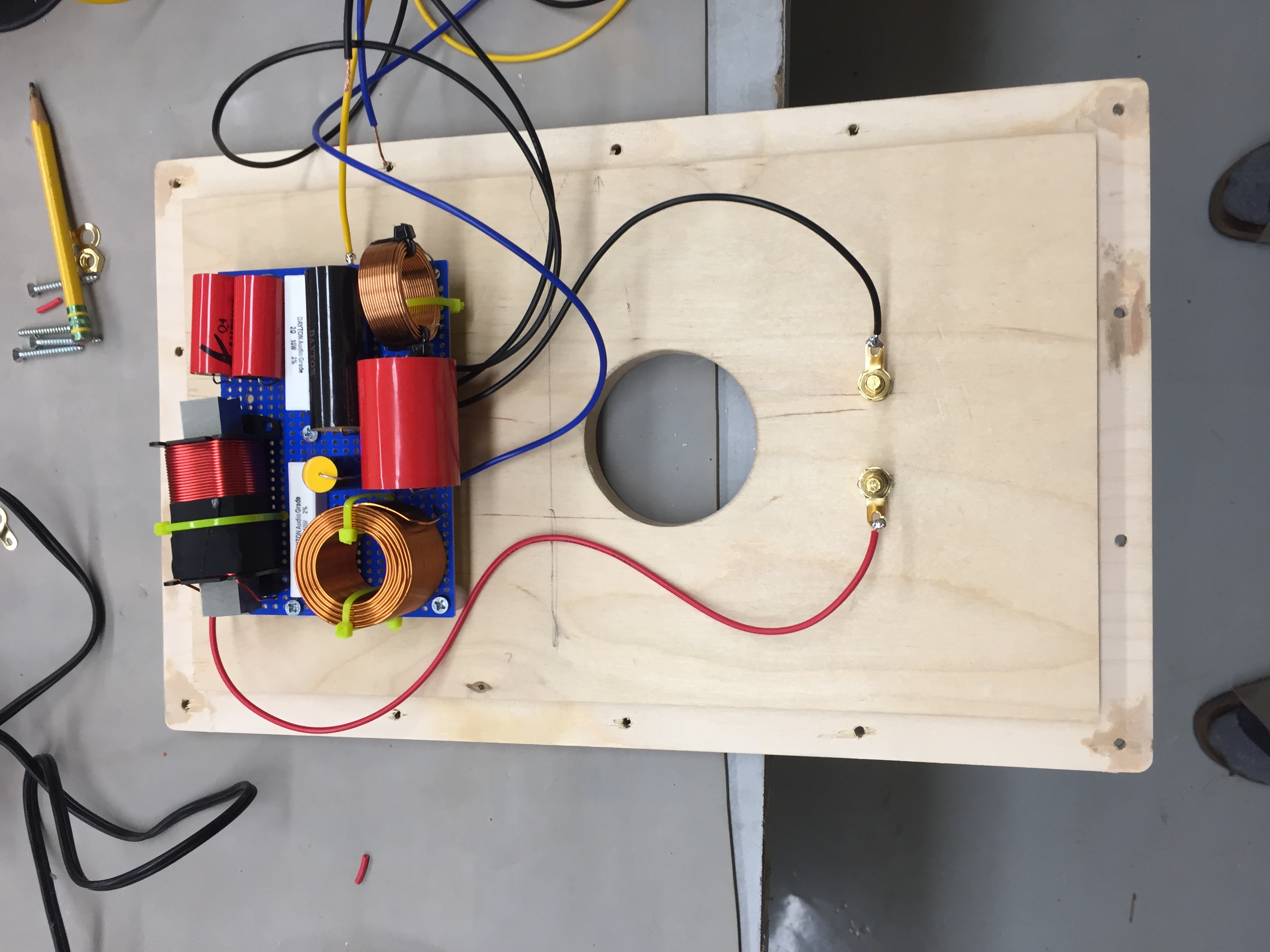
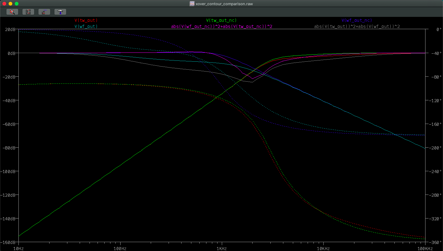
The crossovers were designed by Louis Pandula as passive filters, with a crossover frequency of 2.2kHz, and contour networks to smooth the power across the crossover point. I took these initial designs and simulated them in LTSpice to verify their behavior, as well as to explore the effect of the contour networks. This was a good exercise as there seems to be no set method of choosing contour network component values, and their inclusion should correct the undesirable rising frequency response in two drivers around the crossover frequency, which could cause peaking in the frequencies between 1kHz and 3kHz. From the chosen drivers (Tymphany MDS-P830991 and DaytonAudio ND28F-6) spec sheets, the 2.2kHz crossover point seems like a good fit to me as it captures the flattest response points of each driver.
Step 4: Installing Electrical Components